CAD toolbar
The CAD toolbar enables you to easily use control codes to create line, arc, and polygon features in the map as you measure points, or by drawing line and arc features using feature coded points already in the job.
 To display the toolbar, you can:
- Tap and hold in the map and then select CAD toolbar.
- In the map, tap Options and then select the CAD toolbar check box.
If lines created using the CAD toolbar are not visible in the map, tap ![]() and select Filter. Tap All or tap the CAD linework list item so that a check mark appears next to it.
and select Filter. Tap All or tap the CAD linework list item so that a check mark appears next to it.
- The tools available on the CAD toolbar depend on whether the CAD toolbar is in Measure mode or Drawing mode. To switch between modes, tap
 and then select the required mode.
 - All control codes are available for selection from the CAD toolbar even if the control code is not defined in the selected feature library. When you tap a button the software warns if the control code is not defined in the feature library. The software also warns if the selected feature code is not defined as a line feature.
- The CAD toolbar is only available when you are using General Survey.
You must be in a survey and have a Measure form open to use Measure mode. Measure forms are Measure points, Measure topo, or Measure codes. When you open a Measure form, the CAD toolbar automatically switches to Measure mode.
When connected to an instrument that supports video, you can use the CAD toolbar when you tap ![]() in the map toolbar to switch to the video feed from the map. You must have enabled the CAD toolbar in the map, started a survey, and opened the Measure topo or Measure codes form.
in the map toolbar to switch to the video feed from the map. You must have enabled the CAD toolbar in the map, started a survey, and opened the Measure topo or Measure codes form.
If a Measure form is not open, the CAD toolbar opens in Drawing mode. Drawing mode can only be used in the map, it cannot be used with video.
Control codes defined in the feature library are used to construct line or polygon features using points. Points that have the same line or polygon feature code assigned to them are joined by lines. Trimble Access does not fill polygons.
To create features, the feature library must contain codes defined as lines for the features you want to create, and control codes for the required action to create the feature geometry, such as starting or ending a new join sequence. The example codes in this topic are found in the GlobalFeatures.fxl which is provided with Trimble Business Center.
Start join sequence control codes start lines, and End join sequence control codes end lines. You can use one or the other, or both, depending on the situation or workflow you prefer as there is flexibility in how you use them. For example, you can start lines without a control code, but to start the next line of the same feature code type you can use either the End join sequence control code on the previous/last measurement, or use the Start join sequence control code on the first point of the new line.
For example, to survey the centerliine of a road, the feature library must contain a road centerline (RCL) feature code defined as a Line feature type. To create the centerline feature, before measuring the first point in Measure codes select the RCL feature code and then tap the start join sequence button ![]() on the CAD toolbar. All subsequent points with that are assigned the RCL feature code are added to the line.
on the CAD toolbar. All subsequent points with that are assigned the RCL feature code are added to the line.
You can assign multiple feature codes and control codes to a single point. When assigning more than one feature code, the simplest way to select multiple feature codes is to use the Multi-code button  in the Measure codes form. First tap , and then select the feature code and the control code(s) to apply.
Use the CAD toolbar in Measure mode to create line and polygon features built from points as you measure them. To use Measure mode you must have started a survey and have a Measure form open.
In Measure mode, the CAD toolbar displays 8 configurable buttons for control code functions.
To swap one of the control codes on the toolbar with another one not already assigned, tap and hold any control code on the toolbar and then select the new control code from the list. The selected control code replaces the one you selected on the toolbar.
The following control codes can be selected and added to the CAD toolbar:
| Button | Control code | Button | Control code | |
|---|---|---|---|---|
|
|
Start join sequence |
|
End join sequence |
|
|
|
Start tangential arc |
|
Start non-tangential arc |
|
|
|
End tangential arc |
|
End non-tangential arc |
|
|
|
Start smooth curve |
|
End smooth curve |
|
|
|
Start rectangle |
|
Skip join |
|
|
|
Start circle (center) |
|
Start circle (edge) |
|

|
Join to first (same code) |
|
Join to named point |
|
|
|
Horizontal/vertical offset |
For step by step information on using each function, see To create features as you measure points.
For quick-reference button-press information for example features, see Measuring features quick reference.
- When creating features as you measure points the workflow is slightly different when using the Measure points or Measure topo form, rather than the Measure codes form. In the Measure codes form you will select first the control code action from the CAD toolbar and then select the feature code because selecting the feature code typically triggers the measurement. In the Measure points or Measure topo form, you will first select the line feature code in the Code field and then use the CAD toolbar to append the control code to the Code field.
-
Because control codes are normally only used once at the start or end of an entity, when using the Measure points or Measure topo form the control codes are automatically removed from the Code field once the point is measured. The feature code remains in the Code field, ready for the next point in the feature.
When creating features as you measure points:
- If required, you can select more than one control code for a point. Simply select the required control codes on the toolbar.
- If the feature uses multiple line feature codes, or when stringing features, in the Measure codes form tap the Multi-code button and select the line feature codes first and then select the control code(s) from the CAD toolbar. Buttons for the active control codes are not highlighted yellow when using the Multi-code button.
- Tap Start join sequence
 . The Start join sequence code is added to the Code field.
 -
Select the feature code for the feature in the Measure codes form. This feature code must be defined as a line feature in the feature code library. The line feature code is added to the Code field.
- Measure and store the point.
- Continue to measure points to form the line, assigning each point the same feature code as you used for the start point. As you measure and store each point, each line segment appears in the map.
-
When you reach the final point of the line, tap End join sequence
 . The End join sequence code is added to the Code field.
 Tap End join sequence
to make sure the next point that has the same line feature code will not join to this line. However, if you always use Start join sequence when starting a line sequence, then ending a feature with End join sequence is optional. - Measure and store the point. This last stored point ends the line.
-
Tap Start join sequence
. The Start join sequence code is added to the Code field. A tangential arc must be joined to at least one point so that the tangent information can be calculated.
- Select the feature code for the feature in the Measure codes form. This feature code must be defined as a line feature in the feature code library. The line feature code is added to the Code field.
- Measure at least one point, from which the arc will be drawn tangentially.
-
To start creating the arc, tap Start tangential arc
 . The Start tangential arc code is added to the Code field after the feature code.
 The azimuth between this point and the previous point defines the entry tangent direction.
- Measure and store the point.
-
Tap End tangential arc
 . The End tangential arc code is added to the Code field.
 - Measure and store the point. This last stored point ends the arc.
- If required, continue measuring and storing points for the line feature.
If an arc cannot be computed, the segment is drawn as a dashed red line to indicate that something is wrong. Situations where this will occur are:
- An arc is defined by two points and no tangency information is defined at the entry to the start arc point.
- A two point arc is defined as being tangential at both the start and end but these tangents do not work.
- To include the arc as part of a line, tap Start join sequence. The Start join sequence code is added to the Code field.
- Select the feature code for the feature in the Measure codes form. This feature code must be defined as a line feature in the feature code library. The line feature code is added to the Code field.
- Tap Start non-tangential arc
 . The Start non-tangential arc code is added to the Code field.
 - Measure and store the point.
- Continue to measure points to form the arc, assigning each point the same line feature code as you used for the start point. As you measure and store each point, each arc segment appears in the map.
-
When you reach the final point of the arc, tap End non-tangential arc
 . The End non-tangential arc code is added to the Code field.
 - Measure and store the point. This last stored point ends the arc.
To measure the transition point between two back-to-back arcs, tap both the End arc and the Start arc buttons before measuring the last point of the first arc.
If an arc cannot be computed, such as when only two points of the non-tangential arc have been measured, the segment is drawn as a dashed red line to indicate that something is wrong.
Use the Start smooth curve control code to create a smooth looking curve. Subsequent points are added to the smooth curve until you use the End smooth curve control code.
If any point that makes up the curve has a null elevation then the entire curve is considered to be 2D, and will lie on the groundplane.
- Tap Start smooth curve
 . The Start smooth curve code is added to the Code field.
 - Select the feature code for the feature in the Measure codes form. This feature code must be defined as a line feature in the feature code library. The line feature code is added to the Code field.
- Measure and store the point.
- Continue to measure points to form the curve, assigning each point the same line feature code as you used for the start point. As you measure and store each point, each curve segment appears in the map.
- When you reach the final point of the arc, tap End smooth curve
 . The End smooth curve code is added to the Code field.
 - Measure and store the point. This last stored point ends the line.
To measure a rectangle, you can:
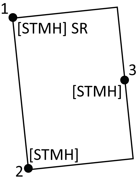
- Measure two points, where the first point (1) defines one corner of the rectangle, the second point (2) defines the next corner of the rectangle, and one of the points includes a width value (3). The first point uses the Start rectangle control code and the line feature code and the second point uses just the line feature code. For one of the points, enter the width value after the line feature code. For example, <Start rectangle> <Line feature> 8 for the first point and then <Line feature> for the second point.
- Measure three points, where the first point (4) defines one corner of the rectangle, the second point (5) defines the next corner of the rectangle, and the third point (6) is used to define the width of the rectangle. The first point uses the Start rectangle control code and the line feature code and the second and third points use just the line feature code.
Rectangles are drawn respecting the elevation of all points.
To measure a rectangle if you do know the width:
- Move to the location of the first corner of the rectangle.
- Tap .
- Select the feature code for the feature in the Measure codes form. This feature code must be defined as a line feature in the feature code library. The line feature code is added to the Code field.
- Tap Start rectangle
 . The Start rectangle code is added to the Code field.
 - Enter the width of the rectangle in the Multi-code field. Enter a positive value to create the rectangle to the right of the line direction, and a negative value to create the rectangle to the left.
- Measure and store the point.
-
Move to the second corner along the length of the rectangle. This point uses the same line feature code you selected for the first point.
- Measure and store the point. This last stored point ends the rectangle, and the rectangle is drawn on the map.
To measure a rectangle if you do not know the width:
- Move to the location of the first corner of the rectangle.
- Tap Start rectangle . The Start rectangle code is added to the Code field.
- Select the feature code for the feature in the Measure codes form. This feature code must be defined as a line feature in the feature code library. The line feature code is added to the Code field.
- Measure and store the point.
-
Move to the second corner along the length of the rectangle. This point uses the same line feature code you selected for the first point.
-
Measure and store the point.
- To measure another point to define the rectangle width, move to a location on the opposite side of the rectangle. This point uses the same line feature code you selected for the first point.
- Measure and store the point. This last stored point ends the rectangle, and the rectangle is drawn on the map.
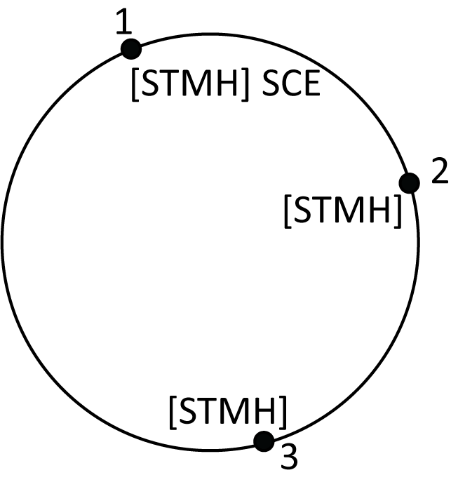
To measure the circle, measure three points that lie on the edge of the circle. The first point uses the line feature code and the Start circle (edge) control code, and the second and third points just use the line feature code.
Circles are drawn horizontal at the elevation of the first point with an elevation.
- At the first point on the circle edge, tap Start circle (edge)
 . The Start circle (edge) code is added to the Code field.
 - Select the feature code for the feature in the Measure codes form. This feature code must be defined as a line feature in the feature code library. The line feature code is added to the Code field.
- Measure and store the point.
- Move to the second point on the circle edge. This point uses the same line feature code you selected for the first point.
- Measure and store the point.
- Move to the third point on the circle edge. This point uses the same line feature code you selected for the first point.
- Measure and store the point. This last stored point ends the circle, and the circle is drawn on the map.
To measure a circle using the center of the circle, you can:
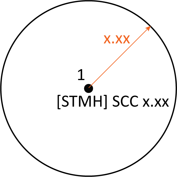
- Measure a single point (1) at the center of the circle where that point uses the Start circle (center) control code and the line feature code, followed by a radius value (2). For example, <Start circle (center)> <Line feature> 8.
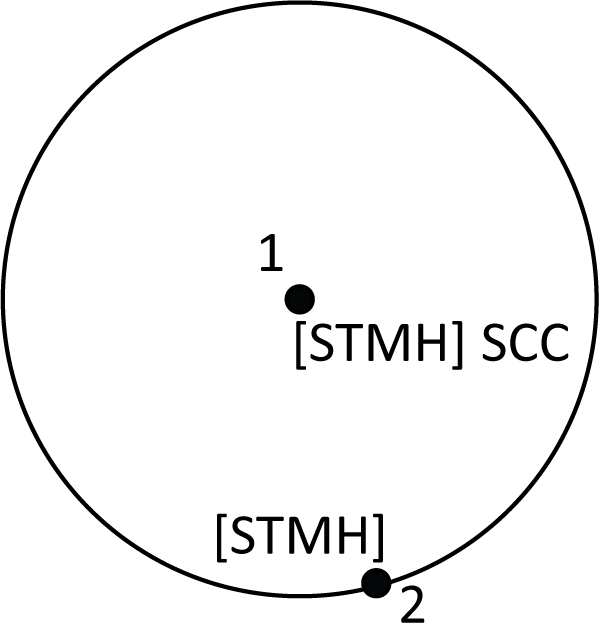
- Measure one point (3) at the center of the circle, and then measure a second point (4) which lies on the edge of the circle and is used to define the radius of the circle. The first point uses the Start circle (center) control code and the line feature code and the second point uses only the line feature code. For example, <Line feature> <Start circle (center)> for the first point and then <Line feature> for the second point.
Circles are drawn horizontal at the elevation of the first point with an elevation.
To measure a circle when you know the radius:
- Tap .
- Select the feature code for the feature in the Measure codes form. This feature code must be defined as a line feature in the feature code library. The line feature code is added to the Code field.
- At the center of the circle, tap Start circle (center)
 . The Start circle (circle) code is added to the Code field.
 -
Enter the radius value in the Multi-code field.
-
Measure and store the point.
The circle is drawn on the map.
To measure a circle when you do not know the radius:
- At the center of the circle, tap Start circle (center). The Start circle (circle) code is added to the Code field.
- Select the feature code for the feature in the Measure codes form. This feature code must be defined as a line feature in the feature code library. The line feature code is added to the Code field.
-
Measure and store the point.
- To measure a point to define the radius, move to a location on the circle edge. This point uses the same line feature code you selected for the first point.
- Measure and store the point. This last point completes the circle, and the circle is drawn on the map.
You can add a horizontal and/or vertical offset value to offset lines and arcs.
You cannot offset linework created using the smooth curve control codes.
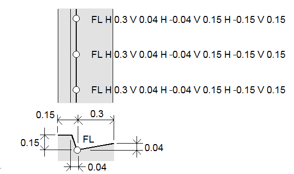
For example, when surveying a curb and gutter you can measure points at the flow line (invert) of the gutter using a line code and then set the horizontal and vertical offset control codes for the curb and gutter. For example, <Line code> <Horizontal offset> 0.3 <Vertical offset> 0.04.
Refer to the following real world example of a curb and gutter where FL is the line code for the flow line, H is the horizontal offset control code and V is the vertical offset control code:
To apply offset values to the next point to be measured:
- Tap Offset
 .
. - From the Number field, select the number of offsets to define.
-
Enter the Horizontal offset and Vertical offset values.
A positive Horizontal offset value offsets to the right of the line direction, a negative value offsets to the left.
A positive Vertical offset value offsets above the line, a negative value offsets below the line.
-
Tap Accept.
The offset information is shown in the Code field, indicating the offset value(s) will be applied to the next measurement.
When applying offsets, Trimble recommends using the Start join sequence
and End join sequence control codes to start and end the line. The End join sequence control code automatically turns off the offset button and removes the offset text.
- To join the current point to a selected point, tap Join to named point
 and then enter the name of the point or select the point in the map and tap Accept.
 - To join a point to the first point in the sequence that has the same line feature code, tap Join to first (same code).
- To measure a point but not join it to the last measured point, tap Skip joinand then measure and store the point.
- To check what the next point name will be, tap . The text after the Next point name menu item indicates the next point name.
- To set the name for the next point, tap and select Next point name.
- Enter the point name and the code for the next point.
- Tap Accept.
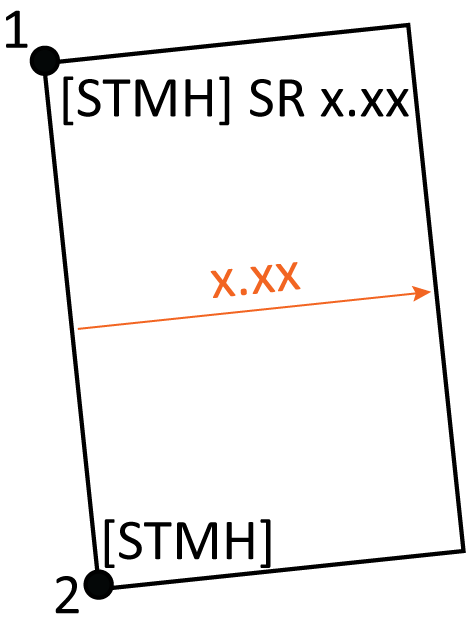
To create back curb (BC) or standard manhole (STMH) features, define the BC and STMH feature codes as lines in the feature library and make sure the feature library includes definitions for the appropriate control codes. The table below shows the codes to select for each point to create each example feature in the Measure codes form and the Measure points or Measure topo form.
| Measure codes | Measure points/Measure topo | To create... |
|---|---|---|
|
|

|
|
|
|
|
|
|
|
OR
|
OR
|
|
|
|
|
|
OR
|
OR
|
|
|
|

|
In Drawing mode, the CAD toolbar has the following buttons:
| Button | Function |
|---|---|
|
|
Draw a line. |
|
|
Draw an arc. |
|
|
Start a new join sequence. |
|
|
Start second arc of a back-to-back arc. |
|
|
End join sequence |
|
|
Delete a line or arc feature. |
|
|
Tap to switch to Measure mode. Measure mode is available only when you have started a survey. |
Use the CAD toolbar in Drawing mode to select existing points in the map and create coded linework between them. You can draw lines, arcs, and back-to-back arcs. You can also delete linework.
- Tap the Draw line button
 .
. - If required, tap the Start join sequence button and then select the feature code for the feature. This feature code must be defined as a line feature in the feature library. The line feature code is added to the Code field.
- In the map, tap the start point of the line sequence you want to create. The feature codes in the Code field are applied only to the start point. The feature code applied to the first point is also applied to the line.
-
Continue to tap points until the line sequence is complete.
As you select each subsequent point, a line is drawn between the two selected points and the first point is then deselected.
- To stop drawing lines, tap the Draw line button again.
- Tap the Draw arc button
 .
. - If required tap the Start join sequence button and then select the feature code for the feature. This feature code must be defined as a line feature in the feature library. The line feature code is added to the Code field.
-
In the map, tap the start point of the arc you want to create.
The points comprising the arc must have been observed consecutively. It will therefore not always be possible to join points with arcs.
-
Continue to tap points until the arc sequence is complete.
As you select each subsequent point, a red dashed line is drawn between the points until enough points are selected so that an arc can be drawn from the first point. As the arc is drawn the previous point is deselected.
- To stop drawing arcs, tap the Draw arc button again.
To draw a back-to-back arc, tap the Back-to-back arc button ![]() after completing the first arc and before selecting the second point of the second arc. After the first part of the arc is drawn between the first and second points of the arc, the button returns to the unselected state.
after completing the first arc and before selecting the second point of the second arc. After the first part of the arc is drawn between the first and second points of the arc, the button returns to the unselected state.
If you have joined points in a continuous line but want to break the line, select the point just before the break and tap End join sequence![]() .
.
The End join sequence code is added to the Code field. The End join sequence code ensures the next point that has the same line feature code will not join to this line.
If the selected point was in the middle of a line, then the next point starts a new line.
-
When you reach the final point of the line, tap End join sequence
. The End join sequence code is added to the Code field. The End join sequence code ensures the next point that has the same line feature code will not join to this line.
- Make sure no buttons in the CAD toolbar are active. Active buttons are colored yellow.
- In the map, select the points, lines or arcs that you want to delete.
- Tap the Delete button
 .
. -
Select the feature(s) to delete from the list and tap Delete.
Lines and arcs are deleted, and feature codes are removed from the affected points. However, the points remain in the job.
