As‑staked point details
As‑staked point details are shown in stakeout reports generated from the Export screen, and they are shown on the Confirm staked deltas screen that appears when you enable View before storage.
To configure As‑staked point details:
- When editing the survey style, tap
and select Settings / Survey styles / <Style name> / Stakeout.
- During stakeout, tap Options.
The As‑staked point details group box has the following settings.
To see the differences between the design point and the as‑staked point before you store the point, select the View before storage check box and then choose one of these options:
- To see the differences every time, set the Horizontal tolerance to 0.000 m.
- To see the differences only if the tolerance is exceeded, set the Horizontal tolerance to a suitable value.
The Stake delta values are reported as differences from the measured/as‑staked point to the design point.
From the Staked deltas format field, select an appropriate display format.
If you are using an R12i receiver and the IMU is aligned, the deltas apply to the pole tip, not the Antenna Phase Center (APC).
The following list shows the translated stakeout formats that are supplied with the language files, and the support offered by those formats:
-
Point – Stake markup
Provides a simplified stakeout display that presents the vertical distance (cut/fill) to the design point. The vertical distance to a DTM will also be displayed if applicable.
-
Point – Stake multiple elevs
Provides a stakeout display that allows you to edit the point design elevation (the cut/fill value will be updated) and entry of up to two extra design elevations with associated vertical offsets and updated cut/fill values.
-
Line – Stake markup
Provides a simplified stakeout display that presents the vertical distance (cut/fill) to the design position. The appropriate station and offset values are reported, based on the selected line stakeout method.
-
Arc – Stake markup
Provides a simplified stakeout display that presents the vertical distance (cut/fill) to the design position. The appropriate station and offset values are reported, based on the selected arc stakeout method.
-
DTM – Stake markup
Provides a simplified stakeout display that presents the vertical distance (cut/fill) to the DTM being staked.
-
Stake manhole inverts
When staking a manhole with multiple inverts from a pipe network LandXML file, provides a simplified stakeout display that uses the extra invert elevations in the LandXML pipe network file to compute their associated vertical offsets and updated cut/fill values on the Confirm staked deltas screen.
If the Roads application is installed, the following additional translated stakeout formats are available:
-
Road – Catch + offsets
Provides details of all the standard road staked deltas plus a list of the horizontal and vertical distances to each of the cross‑section positions from the staked offset position. The reported horizontal and vertical distances include the applied horizontal and vertical construction offsets.
-
Road – Stake markup
Provides a simplified stakeout display that presents the vertical distance (cut/fill) to the road design position. Appropriate station and offset values and cross‑section details (in the case of catch point staking) are reported, based on the road stakeout method.
-
Road – XS details
Provides all the standard road staked deltas details as well as a list of the cross‑section elements (left and right) that define the design cross‑section at the selected station.
If the Pipelines application is installed, the following additional translated stakeout reports are available:
-
Pipelines – Alignment stakeout
Provides details of all the standard alignment staked deltas plus the ahead and behind station values are reported for positions measured in the internal and external angles of non‑tangential intersection points in the alignment.
Select this Staked delta format when staking a pipeline alignment.
-
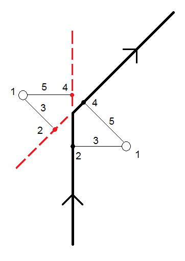
Pipelines – Points stakeout
Provides details of all the standard point staked deltas plus the ahead and behind station values are reported for positions measured in the internal and external angles of non‑tangential intersection points in the alignment.
Refer to the diagram where:

1 Staked point 2 Ahead station 3 Ahead offset 4 Back station 5 Back offset Select this Staked delta format when staking points.
You can set the name of the As‑staked point to be one of the following:
- Design name
- Design name (with prefix)
- Design name (with suffix)
- the next Auto point name
For the design name options that have a prefix or suffix, complete the Prefix/Suffix field as required.
The design name options are available only when staking points.
You can also set the code of the As‑staked point to be one of the following:
- Design name
- Design code
- Last code used
- Design station and offset
- Design file attributes
Select Design file attributes if you are staking an item in a DXF, Shape, LandXML or IFC file and want to save the design file attributes for the selected item with the as-staked point.
The Description defaults as follows:
- When staking a point, line or arc with descriptions, the description of the as‑staked point will default to the description of the design entity unless the As‑staked code is set to Last code used in which case the last used description is used.
- When staking a road using the Roads application, the description will always be the last used independent of the As‑staked code setting.
Set the Store grid deltas check box. Do one of the following:
- Select the check box to display and store the delta northing, delta easting, and delta elevation during stakeout.
- Clear the check box to display and store the deltas as a horizontal distance, vertical distance, and azimuth.
If you use a user definable stakeout report, the Store grid deltas option is not used, unless it is referenced in your report.


