Template positioning examples
A template defines a cross section of the road at a point across the road to define how wide it is at different points. Add a template for each change in width. The template may consist of any number of strings.
A string is the linework connecting adjoining templates. Strings typically define the shoulder, edge of the pavement, curb, and similar features that make up a road. The string name is displayed during stakeout. You can define the string when you add the template.
You can add gaps between strings where required. This is useful when the template does not start at the alignment. A gap is shown as a dashed line from the current string to the previous string. When measuring your position relative to the road, and if your position is in the gap, the V.Dist to the road value is null.
- If the design requires a gap in its definition, set the template field to <None>.
- No interpolation occurs between a null and a valid template.
- Templates are interpolated after superelevation and widening have been applied.
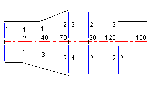
This example explains how positioning of templates and use of interpolation can be used to control an RXL road definition:

Assign the templates at the specified start stations as shown in the following table:
| Start station | Left templates | Right templates |
|---|---|---|
| 0.000 | Template 1 | Template 1 |
| 20.000 | Template 1 | Template 1 |
| 40.000 | Template 1 | <Interpolate> 3 |
| 70.000 | Template 2 | Template 2 |
| 70.005 | Template 2 | <None> 4 |
| 90.000 | Template 2 | Template 2 |
| 120.000 | Template 2 | Template 2 |
| 120.005 | Template 1 | Template 2 |
Right side of the road
On the right side, template 1 is assigned to stations 0 and 20. The road transitions from template 1 at station 20 to template 2 at station 70. Because a template must be assigned at station 40 on the left side, the system template <Interpolate> 3 must be assigned to the right side of the road to maintain correct interpolation.
To correctly represent the gap between stations 70 and 90, the system template <None> 4 is assigned at a nominal distance after station 70 (5 mm). To complete the right side of the road, template 2 is assigned to stations 90, 120, and 120.005.
Left side of the road
On the left side, template 1 is assigned to stations 0, 20, and 40. The road transitions from template 1 at station 40 to template 2 at station 70. To correctly represent the design, template 1 is assigned a nominal distance after station 120 (5 mm).
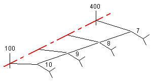
See the following example where the template at station 100 has a string with an elevation of 10.0. The next template is assigned at station 400 and has a string with an elevation of 7.0. The cross section for stations 200 and 300 are interpolated as shown to provide even grading of elevation from station 100 to 400.

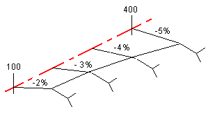
See the following example where the template at station 100 has a string defined by a crossfall of ‑2%. The next template is assigned at station 400 and has string defined by a crossfall of ‑5%. The cross section for stations 200 and 300 are interpolated as shown to provide even grading of cross slope from station 100 to 400.

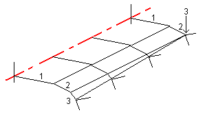
For templates with an unequal number of strings, the template with the least strings has, in effect, a string defined with a zero offset added before the side slope string. The interpolation is then performed given an equal number of strings exist. In the example below, an additional string (3) has automatically been inserted.

By adding strings defined with a zero offset, you can further control the interpolation process to best represent the road design.
If consecutive templates contain side slopes of differing values intermediate stations have side slopes interpolated based on the slope value as a percentage.
For example, if the side slope value at station 600 is 50% (1:2) and at station 800 it is 16.67% (1:6) the side slope value at station 700 will be 50% + 16.7% / 2 = 33.33% (1:3).