To measure a horizontal tilt offset point
When using a GNSS receiver that has IMU tilt compensation enabled and a properly aligned IMU, you can use the Horizontal tilt offset method to measure locations that cannot be occupied by the tip of the pole, for example when measuring the center of a tree or post.
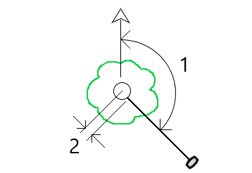
The Horizontal tilt offset method uses IMU tilt compensation to calculate the azimuth of the tilted pole between the Antenna Phase Center (APC) of the GNSS receiver and the pole tip, and then projects the reciprocal of the azimuth (1) forward from the tip at the specified offset distance (2) to compute the offset point:
- Tap
 and select Measure / Measure points, or in the map, with nothing selected, tap Measure.
 - In the Method field, select Hz. tilt offset.
-
Enter the Point name and Code. The point name defaults to the topo point naming sequence.
If the selected code has attributes, the Attrib softkey appears. Tap Attrib and fill out the attribute fields. See To enter attribute values when measuring a point. Tap Store.
- Enter a value in the Antenna height field and make sure that the setting in the Measured to field is set appropriately.
-
Enter a value in the Offset field.
This is the distance from the tip of the pole to the offset point to measure. The offset is represented on the Map by an arrow from the tip position icon.
Usually the pole is tilted toward you – in this case you will enter a positive value. If you need to tilt the pole away from you, then enter a negative value.
-
Align the IMU so that IMU tilt compensation is active, and then position the tip of the pole at the source location for the offset and tap Measure.
-
Tilt the pole more than 15° and sight down the pole at the required azimuth to the offset point.
The offset arrow on the Map is red when the tilt is under 15°. The offset arrow changes to yellow when the tilt is greater than 15° and the azimuth becomes usable. When measuring the status bar shows
 . You must keep the pole tip stationary during measurement, but you can move the GNSS receiver to sight down the pole so that the center of the receiver, the center of the pole, the pole tip, and the offset point being measured (for example, the center of the tree) are in a straight line (on the same azimuth). The azimuth at the time of point storage is the azimuth used for the offset.
 -
When the preset occupation time and precisions have been reached, tap Store.
If Auto store point is enabled the point is automatically stored after the preset conditions are met.
-
Auto store point uses the precision, time, and number of measurements options you have set for topo points. You must ensure that you have sighted in the correct azimuth before the automatic point storage criteria are met. If you are using Auto store point, Trimble recommends that you sight the azimuth correctly before tapping Measure.
-
Auto measure starts when the pole tip becomes stationary. You can move the antenna to sight the azimuth to the offset while keeping the tip stationary. Trimble recommends not using Auto-store and Auto-measure together as there may not be enough time to sight the offset azimuth. If you use full automatic mode you may need to lengthen the measurement time to suit.
-
Vertical offsets are not available with the Hz tilt offset function. The horizontal tilt offset is horizontal only; the computed offset result is at the same elevation as the source tip point measurement.
-
Sighting in the azimuth is the biggest source of error when using this feature. To obtain the correct azimuth, you need to line up the center of the pole with the offset point. For example, at a tilt angle of 25° and an offset vector length of 1.000 m, the difference in azimuth between using one side of the pole to sight the azimuth and the other side of the pole is approximately three degrees, which means the two offset results are about 5 cm apart. If a more accurate offset method is required, use one of the offset methods to compute the point, such as From a baseline.
-
The occupation counter will not count if the pole is within 15° of level. This is because a significant amount of tilt is required for a good azimuth between the APC of the GNSS receiver and the tip of the pole to be determined and sighted by the operator.
-
To ensure the point names of the Hz tilt offset pole tip points are unique, the point names are automatically generated from the GPS time, prefixed with HTO_ denoting horizontal tilt offset.
-
Horizontal tilt offset points are stored as a bearing and distance (polar) in the job file. To see the azimuth and distance entered, change the Coordinate view field in the Options screen to As stored.
-
The source (pole tip) points stored with horizontal tilt offset points are classes as construction points and by default these do not appear on the Map. To view these on the map, change the map filter settings. See Filtering data by measurement type.
