Cogo settings
To change the Cogo settings for the job, in the Create job or Edit job screen, expand the Cogo section.
The following settings are available.
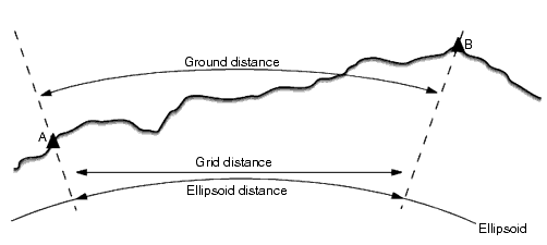
The Distances field specifies how distances are displayed and calculated in the software.
| When Distances are set to... | The length or area is computed... |
|---|---|
| Ground | At the mean ground elevation |
| Ellipsoid | On the ellipsoid surface |
| Grid | Directly off the grid coordinates |
The following diagram shows the options between points A and B.

If the coordinate system for a job is defined as Scale factor only, ellipsoid distances cannot be displayed.
Ground distance
A ground distance is the horizontal distance calculated between the two points at the mean elevation parallel to the chosen ellipsoid.
If an ellipsoid has been defined in the job and the Distances field is set to Ground, the distance is calculated parallel to that. If no ellipsoid has been defined, the WGS‑84 ellipsoid is used.
Ellipsoid distance
If the Distances field is set to Ellipsoid then a correction is applied and all distances are calculated as if on the local ellipsoid, which usually approximates to sea level. If no ellipsoid has been specified, the WGS‑84 ellipsoid is used.
Grid distance
If the Distances field is set to Grid, the grid distance between two points is displayed. This is the simple trigonometrical distance between the two sets of two‑dimensional coordinates. If the coordinate system for the job is defined as Scale factor only, and the Distances field is set to Grid, the Trimble Access software displays ground distances multiplied by the scale factor.
To perform Cogo calculations in a No projection / No datum coordinate system, set the Distances field to Grid. The software then performs standard Cartesian computations. If the grid distances you enter are distances on the ground, the new computed grid coordinates will be ground coordinates.
A grid distance between two measured GNSS points cannot be displayed unless you have specified a datum transformation and a projection, or performed a site calibration.
Curvature correction
In Trimble Access, all ellipsoid and ground distances are parallel to the ellipsoid.
Select the Apply sea level correction check box if the horizontal components of distances measured with a conventional total station should be corrected to their equivalent length on the ellipsoid.
In most cases, Trimble recommends selecting the Apply sea level correction check box to compute the correct geodetic grid coordinates from the total station observations. However, if the local ellipsoid was inflated to provide computed ground coordinates but the point heights were not changed to be in terms of the inflated ellipsoid, do not select sea level correction; for example, when using jobs with Minnesota county coordinate systems.
The sea level correction is carried out using the average height (not elevation) of the line above the local ellipsoid. If both ends of the line have null heights, the default height specified for the job is used to compute this correction.
The formula used for the computation is:
Ellipsoid horizontal distance = HzDist x Radius / (Radius + AvHt)
| HzDist: | Horizontal component of measured distance |
| Radius: | Ellipsoid semi‑major axis |
| AvHt: | Average height above local ellipsoid of the measured line |
- In jobs where the coordinate system is configured to provide ground coordinates, the Apply sea level correction check box is always enabled and cannot be edited. This is because the sea level correction is already applied in the computation of the ground coordinates.
- In a Scale only job, there is no local ellipsoid available because this is not a geodetic projection. In this case, the correction computation defaults to using the semi‑major axis of the WGS‑84 ellipsoid (6378137.0 m) as the radius value. The sea level correction in Scale only jobs also uses the point elevations because there are no ellipsoidal heights available.
- You cannot set a default height for Scale only jobs. This means that if the Apply sea level correction check box is enabled in a Scale only job, you must use 3D points, or null coordinates will be computed because it is not possible to compute the sea level correction.
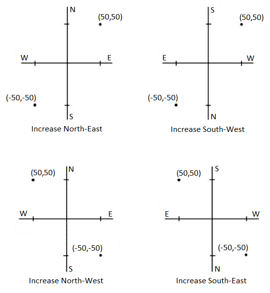
Use the Grid coords field to set the grid coordinates to increase in one of the following sets of directions:
- north and east
- south and west
- north and west
- south and east
The following diagram shows the effect of each setting.

The azimuth displayed and used by the software depends on the coordinate system that you defined for the current job:
- If you defined both a datum transformation and a projection, or if you selected Scale factor only , the grid azimuth is displayed.
- If you defined no datum transformation and/or no projection, the best available azimuth is displayed. A grid azimuth is the first choice, then a local ellipsoidal azimuth, then the WGS‑84 ellipsoid azimuth.
- If you are using a laser rangefinder, the magnetic azimuth is displayed.
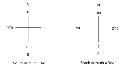
If a south azimuth display is required, set the South azimuth field to Yes. All azimuths still increase clockwise. The following diagram shows the effect of setting the South azimuth fields to No or Yes.

To apply a neighborhood adjustment to all conventional foresight observations made from a Station setup plus or Resection, and to all GPS observations made in a job that has a valid GPS site calibration, select the Apply neighborhood adjustment check box.
Neighborhood adjustment uses the residuals from Station setup plus, Resection or GNSS site calibration to calculate delta grid values to apply to subsequent observations made during the survey. For Neighborhood adjustment to be applied, the station setup or calibration must have at least 3 known points with 2D grid residuals. For more information, visit the Trimble Access Help Portal.
Set the magnetic declination for the local area if magnetic bearings are being used in the Trimble Access software.
The magnetic declination defines the relationship between magnetic north and grid north for the job. Enter a negative value if magnetic north is west of grid north. Enter a positive value if magnetic north is east of grid north. For example, if the compass needle points 7° to the east of grid north, the declination is +7° or 7°E.
- Use the published declination values if available.
- If grid north in the job has been rotated away from true north due to the coordinate system definition (possibly via a GNSS calibration) then this must be allowed for in the magnetic declination specified.
The Averaging field defines how duplicate points are averaged. Select Weighted or Unweighted.
If Weighted is selected, points in an average are weighted as follows:
- GNSS positions use the horizontal and vertical precisions of the observations. Observations that do not have precisions, and keyed‑in points, use 10 mm for horizontal and 20 mm for vertical.
-
For conventional observations that include a measured slope distance, horizontal and vertical standard errors are computed based on the standard errors of the components of the observation.
The standard error used for weighting the horizontal position is a combination of those used for the horizontal direction and horizontal distance weights from the resection calculation.
The Trimble Access software computes an averaged coordinate by averaging the grid coordinates computed from the underlying coordinates or observations. Observations that do not allow a grid coordinate to be resolved (for example, angles only observations) are not included in the average coordinate.
For more information, visit the Trimble Access Help Portal.